Vertical Lever Corkscrew

Client: OXO (USA)   /   Involved in Engineering and Development. Design: Smart Design

Cover Image: Kevin Dooley (Flickr: pagedooley) Attribution 2.0 Generic (CC BY 2.0)

Image credits: OXO Website

Image credits: OXO Website

The corkscrew project presented an exhilarating and unique new challenge in my career, distinct from any other project. This work involved a collaborative effort with engineers from OXO, an esteemed American company renowned for its commitment to Universal Design and Inclusivity, as well as designers from Smart Design, who had already conducted extensive research and design work on the product.

Upon joining the project, it quickly became an opportunity for me to assume the leadership role in executing the product's development - DFM (Design for Manufacturing). This involved tasks such as 3D modeling, meticulous control of tolerances and clearances, conducting numerous tests, reducing parts, correcting important functional and ergonomic issues and engaging in discussions with key stakeholders from both companies.

It is worth noting that other engineers from Smart and OXO had already been working on the engineering aspects of the corkscrew prior to my involvement. Nevertheless, joining the team allowed me to contribute my expertise and play a vital role in shaping the project's execution and bringing it closer to fruition.

00D_DarioNarvaez_Portfolio_OXO_Corkscrew_Covers_WEB.jpg
 

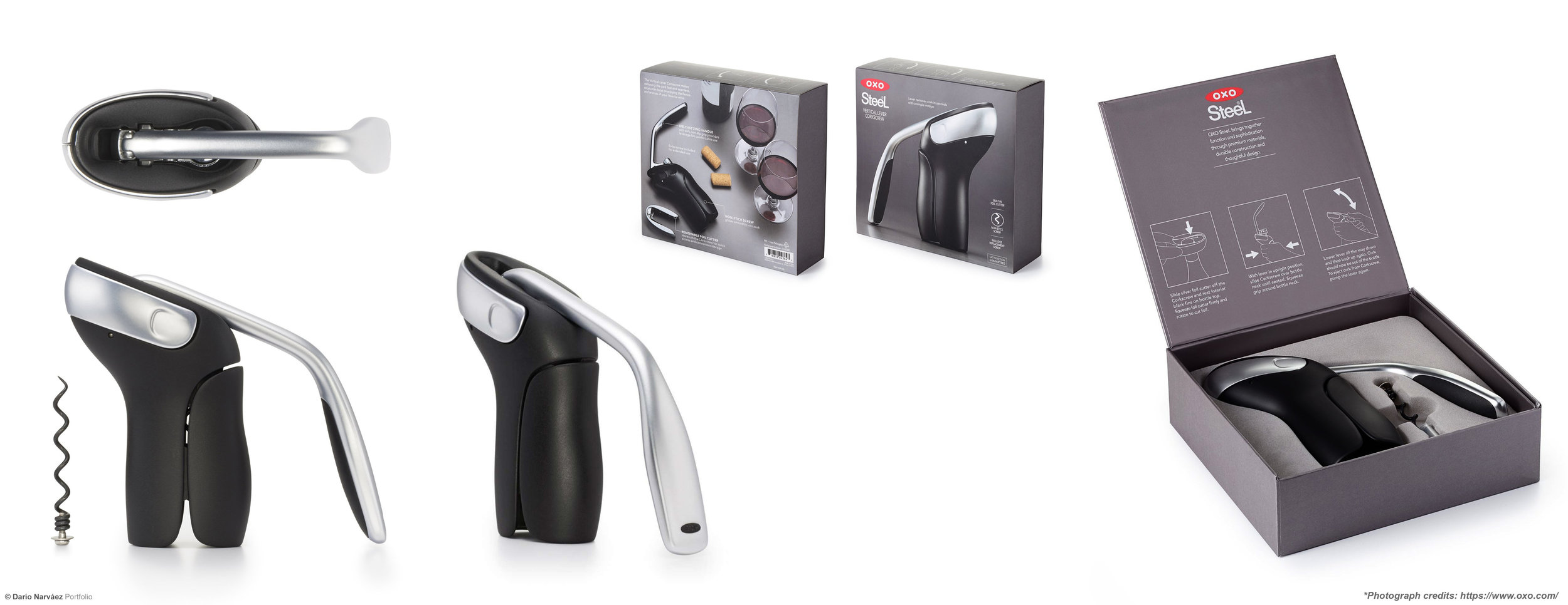
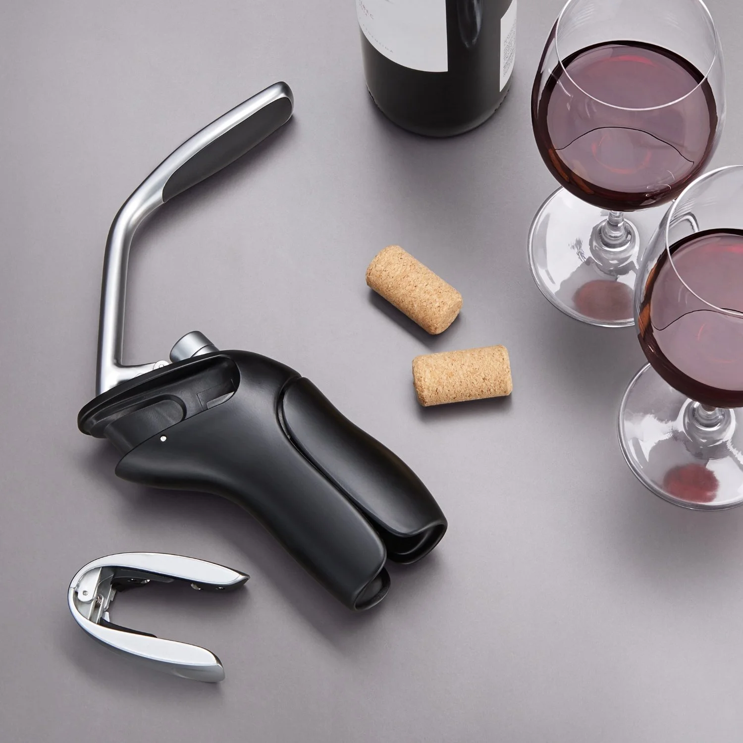
This Corkscrew removes corks smoothly and quickly with two motions. It is composed by a die-cast zinc handle with soft, non-slip grips that provides leverage for comfortable use, and a non-stick screw that glides easily into cork. The cork releases from the Corkscrew with a simple pump of the lever.

The removable foil cutter stores on the Corkscrew for quick access and convenient storage.


Product Development | Initial Data and Prototype

Prototype 1

Initially, my role involved reconstructing a CAD model for the foil cutter, with a specific focus on achieving a resolved and smooth A-Side surface. Subsequent revisions were dedicated to refining the geometry of the foil cutter, particularly in terms of the pinch and release mechanism in relation to the body. Additionally, adjustments were made to the handle profile to ensure that the top could be polished without affecting the split line.

01_DarioNarvaez_Portfolio_OXO_Corkscrew_Engineering_WEB-1.jpg

DFM. After numerous prototypes, I eventually achieved the optimal balance between functionality and manufacturability. It was crucial to carefully consider tight tolerances for the cutting disks and ensure the snap feature worked seamlessly (how the foil cutter was attached to the main body). Additionally, pull angles and assembly processes always were taken into account to ensure smooth operation during manufacturing.

The iterative process and attention to detail played a significant role in refining the design, resulting in a final product that not only met functional requirements but also optimized manufacturability and assembly efficiency.

01_DarioNarvaez_Portfolio_OXO_Corkscrew_Engineering_WEB-2.jpg

Analyzing Data & making changes

“Body” - 2D Study

2D Render Visualization of the proposed changes. At this point, I hadn't worked on the changes on 3D, but It’s important to visualize the changes as real as possible in order to consider other solutions.

After solving the Foil Cutter Area, we realized the body geometry worked just for certain types of bottle necks. I started doing an analysis in 3D with different models of bottles geometries, and I found out that the previous design and engineering was done based on one type of bottle. To solve this issue, the body had to grow horizontally.

Several Iterations took to finally have a consistent CAD Data, feasible and manufacturable. Even though we had a complex tooling process ahead.

We went through several Iterations before having a consistent CAD Data, feasible and manufacturable.

03_DarioNarvaez_Portfolio_OXO_Corkscrew_Engineering_WEB-3.jpg

Throughout the project, numerous prototypes were developed, including prototypes crafted using the actual materials intended for final production. The image showcases a fraction of the prototypes created during the iterative process. It is worth noting that certain components seen in the image were handmade in our workshop to facilitate experimentation and testing, allowing us to evaluate the design's functionality, ergonomics, and overall performance. These physical iterations played a vital role in identifying areas for improvement and validating design decisions, and provided insights that led to subsequent modifications in CAD.

All cork sizes

As a designer, you always want to know how things work...and why they don’t. I got involved in this project in a late phase, initially just trying to solve the “foil cutter” area…then the whole body. Other Engineers were involved in the project before me. Although the project may appear deceptively simple from the outside, it proved to be quite complex. Motivated by a desire to pinpoint the problem, especially considering the base design was rooted in a functioning mechanism, I began a thorough investigation of the original mechanism data provided by the factory. Through this process, I discovered that the issue stemmed from an assembly problem that had persisted since the project's inception. This revelation marked a significant turning point, enabling me to rectify the assembly problem and lay a strong foundation for further enhancements, ensuring the project's success.

The Initial Problem | Analyzing the Data from Factory

Long cork. During testing, we learned about the existence of a long cork of 49mm. Our objective was to achieve effortless bottle opening for any type of bottle and cork size. Building upon the insights gained from our previous 2D analysis, we recognized the need to devise innovative solutions to address this specific challenge.

The complexity of this product arises from various factors, including the abundance of components, the need for precise tolerances, and the utilization of intricate tooling methods. The intricate geometries involved often require specialized tooling actions to account for undercuts. Another significant challenge we encountered was ensuring the stability of the "foil cutter" area. The images below provide a glimpse into the diverse approaches we explored to reinforce the stability and durability of the "foil cutter" area.

Engaging in this project has been a valuable opportunity for personal and professional growth, equipping me with a diverse set of skills that have enriched my design process, collaborating closely with engineers and designers from both OXO and Smart Design, always considering human factors and ergonomics as fundamental aspects of the development process. Recognizing the significance of user experience, we consistently integrated these elements into our decision-making and design choices.